
AN OVERVIEW OF FIBER OPTIC TECHNOLOGY
The use of fiber optics in telecommunications and wide area networking has been common for many years, but more recently fiber optics have become increasingly prevalent in industrial data communications systems as well. High data rate capabilities, noise rejection and electrical isolation are just a few of the important characteristics that make fiber optic technology ideal for use in industrial and commercial systems.
Most often used for point-to-point connections, fiber optic links are being used to extend the distance limitations of RS-232, RS-422/485 and Ethernet systems while ensuring high data rates and minimizing electrical interference. Conventional electrical data signals are converted into a modulated light beam, introduced into the fiber and transported via a very small diameter glass or plastic fiber to a receiver that converts the light back into electrical signals. Fiber's ability to carry the light signal, with very low losses, is based on some fundamental physics associated with the refraction and reflection of light.
FIBER OPTIC PRINCIPLES
Whenever a ray of light passes from one transparent medium to another, the light is affected by the interface between the two materials. This occurs because of the difference in speeds that the light can travel through different materials. Each material can be described in terms of its refractive index, which is the ratio of the speed of light in the material to its speed in free space. The relationship between these two refractive indices determines the critical angle of the interface between the two materials.
There are three actions that can happen when a ray of light hits an interface. Each action depends on the angle of incidence of the ray of light with the interface. If the angle of incidence is less than the critical angle, the light ray will refract, bending toward the material with the higher refractive index. If the angle of incidence is exactly equal to the critical angle the ray of light will travel along the surface of the interface. If the angle of incidence is greater than the critical angle, the ray of light will reflect.
The refractive index of vacuum is considered to be 1. Often, we consider the refractive index of air also to be 1 (although it is actually slightly higher). The refractive index of water is typically about 1.33. Glass has a refractive index in the range of 1.5, a value that can be manipulated by controlling the composition of the glass itself.
FIBER OPTIC CHARACTERISTICS
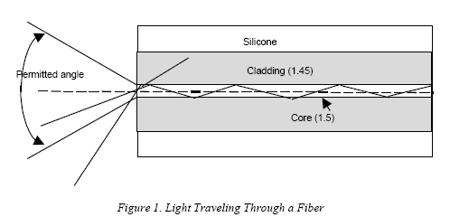
Optical fibers allow data signals to propagate through them by ensuring that the light signal enters the fiber at an angle greater than the critical angle of the interface between two types of glass. As shown in Figure 1, optical fiber is actually made up of three parts. The center core is composed of very pure glass, with a refractive index of 1.5. Core dimensions are usually in the range of 50 to 125 um. The surrounding glass, called cladding, is a slightly less pure glass with a refractive index of 1.45. The diameter of the core and cladding together is in the range of 125 to 440 um. Surrounding the cladding is a protective layer of flexible silicone called the sheath.
When light is introduced into the end of an optical fiber, any ray of light that hits the end of the fiber at an angle greater than the critical angle will propagate through the fiber. Each time it hits the interface between the core and the cladding it is reflected back into the fiber. The angle of acceptance for the fiber is determined by the critical angle of the interface. If this angle is rotated, a cone is generated. Any light falling on the end of the fiber within this cone of acceptance will travel through the fiber. Once the light is inside the fiber it 'bounces' through the core, reflecting inward each time it hits the interface.
Figure 1 illustrates how light rays travel through the fiber, reflecting off the interface. If the physical dimensions of the core are relatively large individual rays of light will enter at slightly different angles and will reflect at different angles. Since they travel different paths through the fiber, the distance they travel also varies. As a result they arrive at the receiver at different times. A pulse signal sent through the fiber will emerge wider than it was sent, deteriorating the quality of the signal. This is called modal dispersion. Another effect that causes deterioration of the signal is chromatic dispersion. Chromatic dispersion is caused by light rays of different wavelengths traveling at different speeds through the fiber. When a series of pulses is sent through the fiber, modal and chromatic dispersion can eventually cause the pulse to merge into one long pulse and the data signal is lost.
Another characteristic of optical fiber is attenuation. Although the glass used in the core of optical fiber is extremely pure, it is not perfect. As a result light can be absorbed within the cable. Other signal losses include bending and scattering losses as well as losses due to connections. Connection loses can be caused by misalignment of the ends of the fiber or end surfaces not properly polished.
